Imaging starter kit
Whether you are brand new to microscopy or already a confirmed user, you will find here a selection of advices and recommendations to perform imaging experiment and analysis in the best conditions.
1. Imaging process
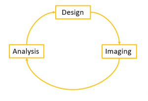
Before starting the imaging of your sample, it is important to have in mind the full imaging process, from the design of the imaging experiment and sample preparation (fluorescent protein, mounting media…) to image analysis. We strongly support you during this whole process, do not hesitate to come and discuss about your project before starting it, or you can also send us an email at orion.cirb@college-de-france.fr.
2. Sample preparation
a. Fluorescent protein
The choice of fluorescent protein (or FP) is critical, and can lead to a common mistake, which is the proximity of emission spectra, and its inherent risk, the crosstalk.
The crosstalk occured when multiple fluorescent proteins are imaged on different detector, but the signal of one fluorescent protein is visible in more than one detector.
In the example below, representing the emission spectra of Alexa Fluor 555 (yellow) and Alexa Fluor 594 (orange), the crosstalk corresponds to the grey area :
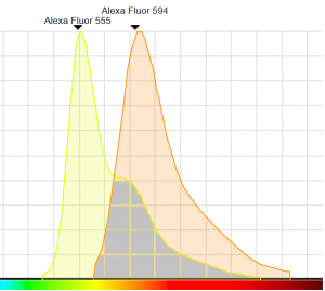
Source : Spectraviewer, ThermoFischer
As you can see, the risk of having fluorescence from Alexa Fluor 555 bleeding into the detection of Alexa Fluor 594 is strong. We recommend you to take a particular care of the emission spectra of your fluorescent protein when you associate them in your experiment design in order to reduce the risk of crosstalk to the minimum. In order to help you make these decisions, please consider visiting the website below :
Another important aspect is the accord of the fluorescent protein with the microscope configuration, in excitation but also in emission. Depending on the technology constraints, some microscope can excite certain category of fluorescent protein or can collect fluorescent emission along certain part of the spectra. Please refer to the imaging facility staff in order to know if the combination of fluorescent protein fit the system available on the facility.
b. Mounting media
The mounting media used to prepare your slide is a crucial parameter of optimisation. The mounting media is the liquid in which your sample is while being imaged. It plays a key role on multiple aspect : it prevents photobleach, drying out and allows long-term storage of your sample.
The refractive index is essential in the choice of the mounting media. The refractive index of the mounting media, the coverslip and the immersion media of the objective need to be as close as possible in order to maintain homogeneity of refractive index. By doing so, the efficiency of light collection is better (less refraction due to index mismatch) and it allows to go deeper in the sample.
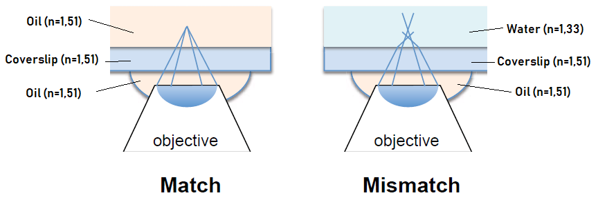
The effectiveness of the mounting media can be observed in its anti-fading properties, to preserve from photobleach. Finally, the long-term storage has to be anticipated, as behaviour of mounting media in time differs from one to another.
On the imaging facility, we advise against mounting media with fluorescent staining included (e.g. Mounting media with DAPI). It is a source of noise on the final image and a poor staining.
c. Coverslip
The coverslip is the interface between the mounting media and the immersion media. A common mistake is to neglect the type of coverslip used for the mounting of the sample, where only some references on the market are dedicated for microscopy observations. The only coverslip compatible with observations through fluorescence microscopy are coverslip # 1,5, which corresponds to a thickness of 0,16-0,18 mm.
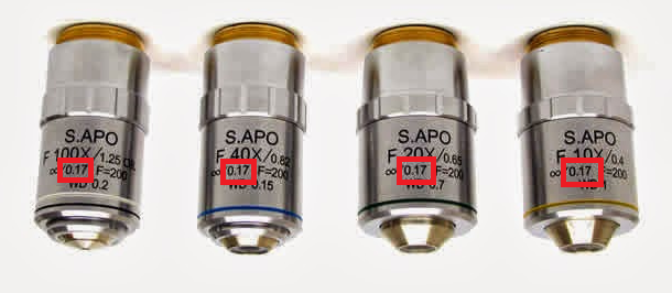
In order to reduce the influence of the coverslip on the light collection efficiency, objectives have been designed with an integrated correction. This correction (in the red square above) applies for a certain coverslip thickness, here of 0,17mm. The use of coverslip #1 leads to poor image quality because of inadapted objective correction, its use should be banned from any sample mounting in the perspective of fluorescence microscopy observations. Please prefer glass coverslip with a thickness #1.5 for your casual microscopy mounting. If the sample will be imaged on a superresolution microscope, the use of coverslip#1.5H is mandatory, as the tolerance on its thickness is higher (0,17 +/-0,005 mm).
Example of working coverslip/dish :
– Fluorodish B35 (here)
– Ibidi Glass bottom dish (here)
– any glass coverslip #1.5 or #1.5H (for superresolution) (here, here or here)
3. Imaging experiment
a. Training
Once you identified the microscope you would use for your experiment, you want to be train to be autonomous on the system.
Please ask for this training when your samples are prepared and you are ready to perform imaging experiment. There is no point to ask for a training few months before the actual use of the microscope, as you would have forgotten most of the training. It is a time loss for you and for the imaging facility staff.
b. Resolution
To perform the highest resolved microscopy acquisition, only two criteria has to be taken into account : the highest wavelength involved and the numerical aperture (or NA) of the objective. Those two criteria are necessary in the calculation of the resolution of the microscope :

It becomes clear that magnification of the objective is not a decisive factor in the final resolution of the image.
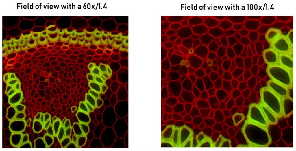
Above is a sample acquired with a 60 x objective and a numerical aperture of 1,4 next to the same sample acquired with a 100 x objective and a numerical aperture of 1,4. The resolution of the two images is strictly the same, the only thing that changes is the size of the field of view.
Once the two criteria are optimized, the pixel of the detector must have a certain size to be able to restitute the highest resolution achieved. This size is determined by the Nyquist criterion. The Nyquist criterion requires a pixel size equal to twice the resolution of the microscope. In laser-scanning microscopy (e.g. confocal microscope, two-photon microscope…) where the light is detected by a detector without spatial information, the pixel size can be modulated by the zoom factor or the number of pixel in the image. In camera-based microscopy (e.g. spinning-disk microscopy, widefield microscopy), the pixel size of the image is defined by this formula :

where the physical pixel size corresponds to the size of the pixel on the matrix of the camera (available on the manufacturer website).
c. Experiment strategies
I. Colocalization experiment
While doing colocalization experiment, the crosstalk of fluorescent protein (cf 2.a) can skew the result, exhibiting a strong colocalization where it is only a bleedthrough of one channel into the other. To overcome this risk, we advise you to perform the experiment with single-label sample first, to ensure that there is no bleedthrough of fluorescence into the wrong channel of detection. If there is bleedthrough, it is recommended to adjust the experiment settings (eg. spectral domain of detection, laser power… ) or to change one of the fluorescent protein.
II. Intensity quantification
If you need to quantify the intensity of fluorescence of one or more fluorescent protein present in your sample, you want to avoid external fluctuations from one experiment to another. These external fluctuations can come from the laser power, the sensitivity of the detection…
The best solution to reduce the influence of this fluctuations is to mix sample conditions for each session of microscopy. With such a mix, each condition will be affected equally on the session of microscopy, leading to better reproducibility in the experiment and stronger result.
4. Image analysis
The image analysis strategy has to be design before any acquisition on microscopes, as it can modify the way you perform your images. Do not hesitate to take appointment with the imaging facility staff to establish the best image analysis strategy and imaging experiment.
Either for visualisation or for analysis, we strongly recommend the use of the software Fiji, a distribution ImageJ bundling many plugins in order to facilitate image manipulation.

The website to download the latest version of Fiji can be found here.
A wide selection of tutorials can be found here.
Analysis workstation are available on the imaging facility. The computationnal capabilities of these computer are by far better than the current desk computer. There is no training necessary to have access to this computer. However, it is strongly advised to contact the imaging facility staff if you plan to use software like Imaris (for 3D visualisation and analysis) or Huygens (for deconvolution), a training is essential to effectively use these softwares.